The Westgate Electric Tramway
A 1/16th scale model garden tramway in North Kent
Welcome to the page about the Westgate Electric Tramway, a short single track tramway built up against an old stone wall that separates my flat from the busy North Kent mainline from Victoria to Margate.
I've included sections on building the tramway, restoring and building the tramcars, and other bits and pieces that may be of interest.

CLICKING ON ANY OF THE PHOTOGRAPHS WILL BRING UP A LARGER IMAGE
You can follow progress so far by using these link buttons
Base and track construction
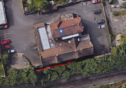
The location is an alleyway that served the old school in Westgate. It now divides the property from the North Kent mainline.
The tramway is fairly short - about 36ft and is end to end, the alleyway being not wide enough for a turning circle. I live in the flat in ther bottom left hand corner of the property so the tramway passes my bedroom window.


Click on any of the pictures for a larger image
The wood arrived on the 17th September 2020. The wall was cleaned off and the boards laid up to get an idea of the length of the tramway.
I screwed the metal shelf brackets to the wall and laid the boards on them. Where boards were to be joined I screwed
short boards underneath as joiners.


With the final board fixed in place this was the trackbed as seen from the eastern end.
THe completed boards given a liberal coat of preservative. The brass rail can be seen bundled on top of the white draws.
Getting on with the boards. The 5" gauge track was for an abortive line in a small garden centre
With the baseboards in place it was time to start track laying. I wanted to build the tramway on a budget so my initial thought was to 3D print the rail chairs and nail them direct to the baseboards. This had worked well on my short indoor test track so I had no problems with the idea it would be OK outside. Thus started the 3D phase.


The method of laying track. The printed rail chairs were slid on to the bullhead rail and spaced out enough to give some stability . Each rail chair was held in place with two small brass pins. Even if I say so myself they looked quite smart, although black would have been better. As I had both standard and narrow gauge trams I laid the mainline as dual gauge track. The middle picture shows the board widening at the east end to allow the siding to be laid in. I did this at both ends with the width extension screwed on to outrigeers fixed to the main boards. The third picture shows the dual gauge point arrangement (and it worked)


With the track down it was time to think about overhead. Traction poles were made from 14mm dowel with 9mm cross arms. A printed bracket and finial finished the pole off. I had always intended the tramway to be a two wire system with one for up traffic and one for down. My good pal Noel Dollimore made me some ears and these were bolted up through the cross arm with a 3D printed spacer. At each end a firmly placed traction pole was fitted with fairly heavy springs to keep the stainless binding wire I was using for overhead under tension. Finally a view of the tramway ready for action. (click on the pictures for a larger image)


During a fairly mild winter the track remained fairly steady to gauge but I did find that with the varying temperaturs and expansion of the wooden board the pins tended to work loose and the chairs moved a bit. To counteract this I bought some small sheets of copper clad paxoline and sliced them up to make sleepers. These sleepers I soldered to the track and various spacings to take the strain off the 3D chairs.
The first of the copper clad sleepers on the dueal gauge section soldered to the brass rail. I initially used a cheap blow torch which was a waste of time. I have now purchased a slightly more expensive one and am delighted to say it works very well. The white rail chairs have had a coat of dark grey and look a bit better. The point was the next to tackle but I was still getting problems with the chairs coming loose from the boards. My proposed solution was the integrated sleeper and chairs which allowed a more positive fixing to the boards and also made dual gauge track a lot easier to make - problem solved? not really.


The combined sleepers and chairs replaced the individual chairs and seemed to work very well. The gauging was fine even on the dual gauge sections, and my thoughts turned to other things such as lighting. Tony Hildreth donated some substantial spring loaded buffer stops - one set was immediately located at the west end and I added a red stop light. This and the street lamps used 3D printed heads and basis and looked quite effective.
The overall shot gives an idea of the re-sleepered layout (click on any picture for a bigger image). Time to relax - WRONG!


Tram tests were taken regularly to check for any gauging problems and all seemed well. On a particularly hot day when my friend Noel had come over to run his Feltham it kept derailing. The problem was that in the heat the sleepers, which were printed using PLA filament, became very soft and distorted. Advise was sought from them that know about such things and I was advised to print in PETG as that has a much better tolerance to mid and high range temperatures. After due consideration I decided to scrap the 3D sleepers and instead invested in more copper clad. Thus I painstakingly replaced the plastic with copper. Having found a few more lengths of brass bullhead in the workshop (shed) I also embarked on extending the tramway at the eastern end. Initially the siding and then the main line were added to, which now means I can hold up to six trams in the extension and 2 at the west end - so a 7 car service is possible if the need arose. THe track is sectioned rather than the overhead with local switches fitted to the edge of the board adjacent to the section breaks.


A few words about the power distribution. In the beginning I purchased a cheap 24v DC power supply which was monuted on the wall in the shed at the west end. Noel had provided me with a reversing controller so I ran the + and - from the power unit to a point midway down the layout. It terminated in a plastic takeaway box from where a short flying lead could be plugged in to the side of the controller. From the controller another short flying lead can be plugged in to the switch box that directs power to either of the two overhead wires. This box is the one that can be seen top right in the first picture. A simple changeover switch is used to connect either the back or front wire to the power. The centre picture shows one of the section switches. The F & B deliniating which track it refers to.
This was fine for one man operation as the controller had a reversing switch meaning I didn't have to reverse it at the tram - it was therefore possible to run a tram to one end and then bring it back without turning the pole (well I'm getting old!). However, I wanted a system where we could have an operator at each end for those occasions when there was more than me operating. I am not a great electrical engineer and electronics are the tool of the devil - so I asked Noel to design a system, which he did.
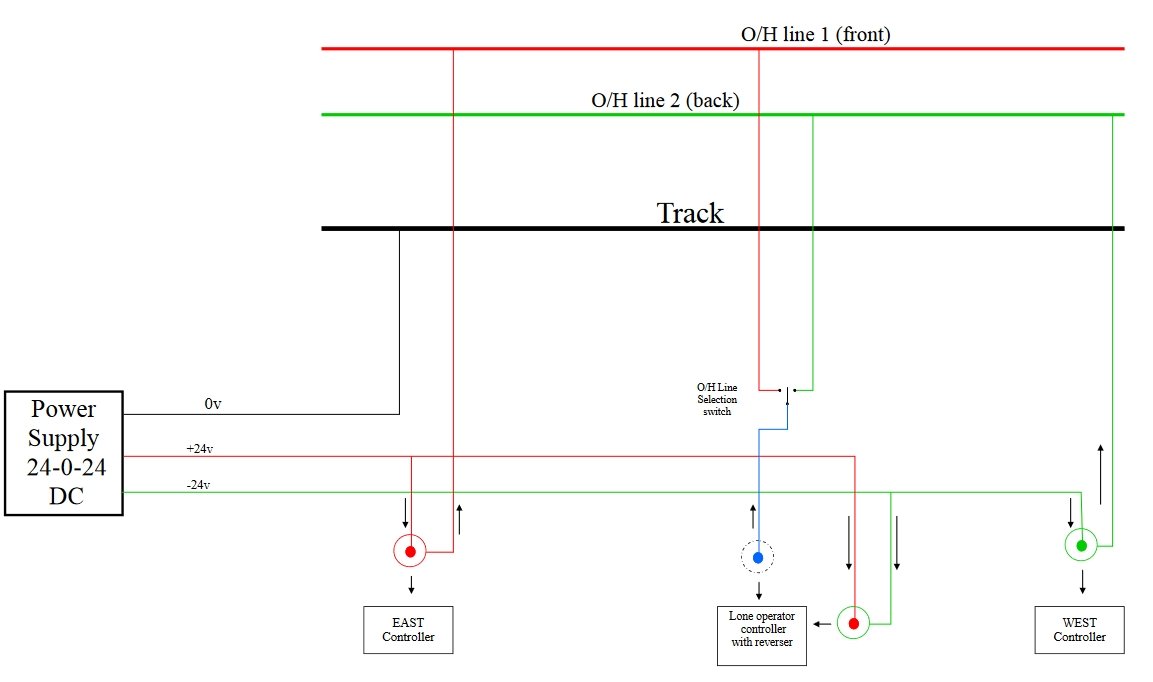
We now have two controllers, the original and a nice new one. The original has been modified for use with the new system, the only difference being that with two person operation the reversing switch is switched to mid position. This is normally used at the east end and the new one at the west. For one man operation I still use the old one plugged in to the original takeway box. The original power unit has now been replaced by a purpose built 24-0-24 unit and there was a bit more wiring to do as it now needed feeds at both ends of the layout. For those that understand it or want to know what has been done here is the wiring diagram.


Finally a few 'chamber of horrors' (my pointwork) pictures and explanation. The picture on the left is the east end point. Originally both points were two blade operation sprung for the sidings. All very well but as the dual gauge was only on the main line it did leave itself open to the Birmingham car ending up off the track. I've now converted both to single blade operation sprung for the main line. The bell crank on both east and west point is a bit Fred Karno but by taking some binding wire from it to the mid point I can operate both points from the solo driving position. For two person operation you just have to hold the point over bt pressure on the actuating arm. As you can see from the scorch marks on the wood there has been a lot of experimentation to get the points right - but they do work and derailments are few and far between, although one or two trams do bounce a bit over the frog.
For two person operation at each end the controller is single wired to the appropriate overhead. The set up is that the trams always travel towards the controller, which stops the chance of a runaway clouting the buffers! For solo operation the two feed wires from the back and front switch box are fed to the two overheads via the traction pole closest to the mid point as seen in the right hand picture - it aint pretty but it works for me.
The Westgate Electric Tramways Fleet
BIRMINGHAM 405
It all started on the 22nd of May 2020 when a large box arrived containing a badly damaged 1/16th scale model of a Birmingham 4 wheeler.


I didn't take too many pictures during the restoration of Birmingham 405. The picture on the left shows the 'bits'. It had obviously been dropped several times and one platform had become distorted and detached, while the other was a bit bent. The glue holding the seats in place had dried out and some of the seats were broken, some of the glazing was hanging on - but it was complete and the truck and trolley pole were complete. A pattern was drawn up of the broken seats parts and new parts printed, the dash was tweaked (carefully) and reinforcing strips bolted to hold it in place. The slight twist in the upper deck was more difficult to rectify but I got there in the end. The centre picture shows the first attempt at ensuring it all went together and the third shows the completed tram on a short length of narrow gauge track. Surprisingly the tram moved easily on 12volts and I was well pleased with the result.
As this was narrow gauge I then thought I might have a go at building a Thanet tram......but:
____________________________________________________________________________________________________________
THE OPEN TOPPER


It arrived on the 18th September 2020 and straight from the box it was obvious this was a well built model, and a bargain for what I paid. The truck was good and only lacked a motor. It had been fitted with very heavy springs, which I have replaced with ones with a bit of give in them.
I saw a fairly random advert for an open top tram for sale at a price I thought was fair. It was a display model rather than an operational one and had no motors or wiring. The dimensions were a bit random but I thought it worth a punt at the price. Fortunately my hunch turned out a winner........now to see how difficult it would be to turn it in to a runner.


Having contacted Simon Cole I managed to acquire a 24v motor and a set of gears. I then printed a motor mount to see if I could get the tram moving. This mount worked well but has since been replaced by a better design.
The paintwork was very well applied so I carefully split the upper and lower decks to fit a wire from the trolley pole to the motor via the obligatory double pole double throw reversing switch. The trolley pole and stand were fixed but again it looked as if it had been built for possible conversion to operation. It didn't take long to convert it to a fully sprung unit. Once reassembled I added some adverts and destinations based on the ficticious Faversham Electric Tramway, which was built to transport workers from the railway station to the gunpowder works. The tram was finally track tested succesfully on 17th October 2020.
____________________________________________________________________________________________________________
KINVER SINGLE DECKER


The first picture shows it as arrived and held together with loads of Blutack just so I could photograph what it should look like. It seemed most of the bits were there but not neccesarily in the right order! The middle picture shows most of the bits laid out. One of the big problems turned out to be that the roof would not come off so any work needed in that area had to be done through the clerestory. It was built by the late Walter Amos who I think must have had shares in both varnish and a cheap glue as these were used in abundance. The truck was a strange thing constructed mainly of aluminium and fitted with two dodgy looking capsule motors. How the body fitted to the truck was, and still is, a bit of a mystery.
Just as the overhaul of the open topper was coming to an end I heard that there were the reamins of several 1/16th trams on the market. They had been stored for many years at the Heaton Park Tramway and all were in a poor shape. Some had already gone but I made an offer for the remains of a single deck 4 wheeler. It arrived with me in early November and to be honest I did wonder if I had bitten off more than I could chew!


Like the body the truck had been liberally plastered with paint. There was nothing for it but to strip it right down and start from scratch. Having used as much paint stripper as Walter used varnish it all fell apart and I was able to clean everyting, repair the broken bits and reassemble the truck. Unfortunately the motors proved worn out - the car is quite heavily built and the motors just hadn't got the guts to keep it moving. In the end I replaced the wheelsets and gears and fitted just one of the 5U 24v motors driving one axle, which has proved very much man enough.
Also missing were three of the four axleboxes but by using the one remaining one I was able to draw up a replacement file and 3D print replacements.
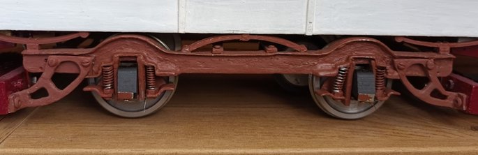
A side view of the truck under the tram showing the printed dummy springs between the truck and the body, and the replacement 3D printed axle boxes.


Turning to the body it required three applications of neat paint stripper to remove the varnish, but I eventually got there and the saloon was given a coat of grey primer.


I went for the yellow and white livery as these were the colours it arrived in. Having looked at various Kinver pictures I went for a grey roof, but have since found that this particular car did keep the green roof, so it is in my mind to return it to green. It's now fitted with a trolley pole made by my friend Noel and runs very well. I've also fitted internal lights fed from a 3v battery hidden in the clerestory.
___________________________________________________________________________________________________________
THE DEMI-CAR


The truck sides just fitted diagonally on the printing plate. The axle boxes slide up and down easily in the horns and include oil holes and indents to hold the springs. The assembled truck sides show how it fits together with heavyweight brass strip, which was drilled to take the riding springs. THe picture on the right shows the bits needed to progress the truck, including the motor and mount.


With the wheels, axles and gear assembled it was possible to balance the parts together to measure up for cross bracing, which is brass strip glued and bolted to the truck sides. Now it was time to have a go at the saloon construction.
When I bid for the Kinver car I had really wanted one of the Demi Cars but they had already gone. After a little thought about it I decided that by now I could probably have a go at scratch building one. I decided to incorporate what I had learned with the limitations of my 3D printer to try to use it for some of the otherwise labour intensive parts. The great thing about printing is that once you have drawn out the part as a printable file you can make as many as you want and they will all be the same. But first I needed to think about a suitable truck - again I turned to the trusty printer.


The seat supports and the seats themselves add the strength to the saloon. The seats are solid as are the internal bulkheads These were printed as pairs with one a mirror image of the other. A piece of acetate was then sandwiched between them. This made a very strong assembly.
These six pictures show the construction method. It's really the same as you would use with wood and card but I've used 3D printed parts, plasticard and Palight.


The saloon nears completion so it was time to fit the truck. This was held in place by brass brackets, one of which can be seen at the right hand end. With its complex curves and clerestory the roof presented lots of challenges. In hindsight I think it would have been better to carve the ends from softwood but I persevered using thin plasticard and it didn't turn out too bad.


11th MAY 2021
___________________________________________________________________________________________________________________________
THE M CLASS
Building a double decker, an ex LCC M Class 4 wheeler, using 3d printed parts. I have always liked the M as they were shipped in to Erith and Bexley by LPTB in 1933 to replace the system's aged open toppers.
So the build begins......click on any of the pictures for a larger image.


Lower deck saloon taking shape - pictures clockwise from top left: The framing for the sides showing 3d printed uprights and wooden stringers.A side plated with Palight (available from 4D Models). A framed side, finished side and the bulkheads. The toplights on the sides were 3d printed as were the shaped waist rails. A test fit of side and bulkhead. The saloon box complete with seats standing on the truck.


Clockwise from top left: 3d printed bits for the platforms. The dash is Palight carefully curved to shape - this worked quite nicely but for the other end I actually printed the dash. Platform and dash undercoated. Both dash fitted. Stairs are 3d prints with plasticard edging strips. Was quite pleased how they looked with a coat of red.


Double-click here to add your own text.
Clockwise from top left: Test fit for the upper deck. Upper deck showing construction, both ends were 3d printed as were the uprights - the framing was plated with plasicard and the detail was added with the same. The drop frames were printed and test fitted before glazing and painting. The great thing about printing is that it takes the repetition out of the job - here are the constituent parts of the upper deck seats. A flip over seat before final assembly and painting. Ready for the passengers.


Before going any further a few words about the truck. Clockwise from top left: My printer bed was not big enough to print the truck side in one piece so it was printed in two halves and then bolted together using brass strip as the joining piece. The print of the axle box which slides up and down in the horn guides very smoothly. The assembled truck frame waiting wheelsets. The wheelsets, which were left over from the Kinver single decker when I rebuilt it - the brace in the middle is there to stop the truck flexing while testing it through my points. The two motors were very cheap Chinese ones and I had to sleeve the motor shafts to take the old gears. The motors in place, they were eventually wired in series to keep the speed down a bit! Don't forget you can click on any of these pictures to see a larger uncropped version.


Clockwise from top left: Looking at the upper deck showing the fairly basic detail inside and the two wooden formers that are in place to keep the sides from bowing inwards and to screw the roof to. Another view of the roof fixings. The roof being test fitted, power is distributed using copper tape and nickel silver sprung tabs. Now fitted with adverts, which I drew out in Corel Draw, printed on to photo paper and sprayed with matt acrylic clear varnish before sticking in place - still bits to finish like controllers, steps, handrails etc. On test in the garden using a trolley pole I borrowed from the demi car, and now complete with handrails, controllers, mag brakes, steps, headlamps (thanks Noel). Taking its place alongside Birmingham 405 - an interesting comparison in standard and narrow gauge. ITS NICE TO HAVE A RED & CREAM IN THE FLEET.
AROUND THE LINE & I SPY VISITORS
To finish this look at the Westgate Electric Tramway here's a selection of pictures taken on the line.


A few shots from around the tramway featuring my trams, but we are happy to welcome visitors if they want to bring a tram to try out. The only problem is that the area the tramway is in is quite small so we can't do large parties but if one or two people want to come along then email me at dereksmith@westgateonsea.net and we will try to arrange something.
One regular visitor is my good friend Noel and here's a few pictures from his visits.


Noel is now the custodian of the experimental Feltham built by Tony Hildreth and its always a welcome visitor. Noel has returned the tram to the original MET livery and very smart it looks as well. This was one of only two Felthams built with the lower cab than the production versions. As all my cars are 4 wheelers it is a bit of a challenge to get all 8 wheels on the track in one go! In the final picture my Kinver car and the Feltham are posed along with the truck Noel has built for his single deck E Class - more pictures below.


Like me, Noel has been pushing the boundaries in construction using 3d printing for a lot of the parts. This has led to a fairly lightweight tram. The truck sides and motor mounts are also printed keeping the weight further down so that we can experiment with smaller less expensive motors. At the time of posting this the E is not yet quite finished but it runs extremely well. With the long overhang I was a bit worried it might clout the wall coming out of the sidings. but it misses (just about) so all is well. Although I've fitted lights to some of my trams this E class has a full complement including the under the canopy lights.
The final picture: Noel has also recently become the custodian of Tony's 'what might have been' works car. We have posed it on the layout but it requires a bit of work to get it to join the operational fleet.